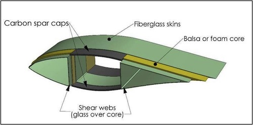
What are Carbon Fiber Spar Caps?
Spar caps are long, narrow strips at the top and bottom of the blade’s airfoil-shaped cross-section.
They are typically embedded within the blade made of a carbon fiber composite material.
Use in Wind Blades:
Load Bearing: The primary function of the spar caps is to bear the loads (both gravitational and wind-induced) that the blades experience. They ensure the blade maintains its shape and structural integrity even under extreme conditions.
Enhanced Performance: Carbon fiber’s high stiffness-to-weight ratio allows for longer, more slender blade designs without a proportional increase in weight. This results in more efficient turbines capable of capturing more wind energy.
Durability and Longevity: Carbon fiber is resistant to fatigue and corrosion, which helps extend the lifespan of wind blades, even in harsh weather conditions.
Advantages of Carbon Fiber Spar Caps
Increased Efficiency: Blades with carbon fiber spar caps can be made longer than those with traditional materials, like glass fiber, enhancing wind turbines’ efficiency and energy output.
Weight Reduction: Carbon fiber is lighter than many other materials with comparable strength, leading to lighter blades that put less stress on the turbine’s components, like the gearbox and bearings.
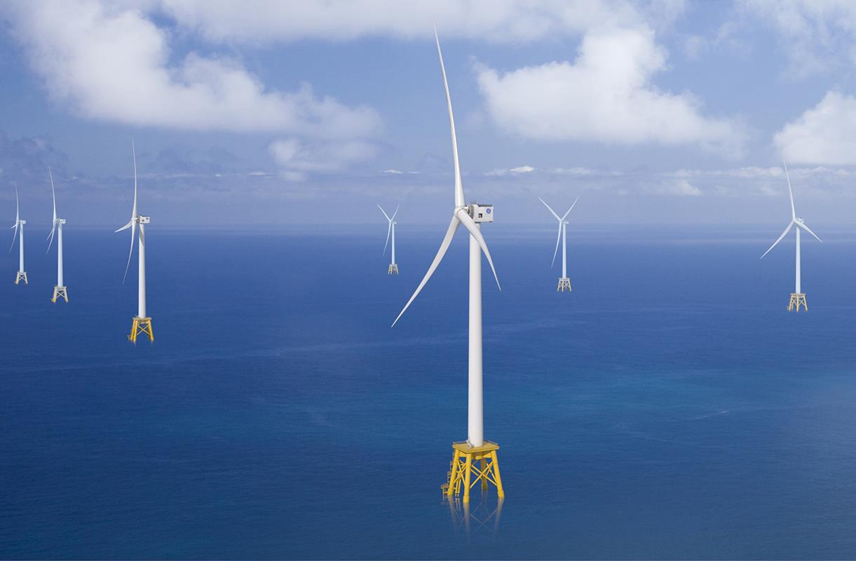
Off-Shore Wind Turbine Park (Courtesy of LM Wind Blade)
Improved Strength and Stiffness: Carbon fiber provides superior strength and stiffness, crucial for maintaining blade shape and performance, especially for larger turbines.
Design Flexibility: Using carbon fiber allows for more innovative and effective blade designs, accommodating the evolving needs of wind turbine technology.
Considerations and Challenges
Cost: Carbon fiber materials are generally more expensive than other alternatives like glass fiber. The initial investment for turbines with carbon fiber blades is higher.
Manufacturing Complexity: Producing and embedding carbon fiber spar caps into blades requires precise and controlled manufacturing processes.
Repair and Recycling: Repairing carbon fiber components can be more challenging and costly than traditional materials. Additionally, recycling carbon fiber composites is more complex.
Types of Carbon Fiber Spar Caps
The types of carbon fiber spar caps for wind turbine blades are generally categorized based on their structural design, the manufacturing process used, and the specific types of carbon fiber materials incorporated. Here are the primary variations you’ll find:
1. Infused Spar Caps:
These are made using infusion techniques, where dry carbon fiber materials are laid into the mold and infused with resin under vacuum pressure.
Infusion can be cost-effective and suitable for large structures, but controlling the quality and consistency of the resin flow can be challenging.
2. Prepreg Spar Caps:
Made from pre-impregnated carbon fibers (prepregs), where the resin matrix is already applied to the carbon fibers in a controlled factory setting.
Offers excellent quality and uniformity with high strength and stiffness. The manufacturing process is cleaner and more controlled, but the material costs and required curing processes can be more expensive.
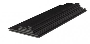
3. Pultruded Spar Caps:
Created through the pultrusion process, where carbon fibers are pulled through a resin bath and then through a heated die to cure.
Pultruded spar caps are continuous and can be made to various lengths. They offer consistent quality and are efficient to produce but are generally limited to simpler cross-sectional shapes.
Considerations for Selection
Each type of spar cap has its own set of advantages and trade-offs. The choice depends on a complex interplay of factors, including performance requirements, cost, manufacturing capabilities, and the specific design of the wind turbine blade. As technology advances, new methods and materials continue to emerge, pushing the boundaries of what’s possible in wind turbine efficiency and reliability.
Currently, pultruded spar caps are the trending technology in the wind blade community. Let’s have a closer look at this spar cap option:
Advantages of Pultruded Spar Caps
Efficient and Continuous: Pultrusion is highly efficient and can continuously produce long lengths of material.
High Strength and Consistency: The process yields products that are consistent in quality, with high strength and stiffness due to the alignment of the fibers.
Cost-Effective: Once set up, pultrusion is relatively low-cost for mass production, especially for standard profiles.
Considerations
Limited Shapes: The cross-sectional shape is constant along the length, and complex shapes might be challenging or impossible to achieve.
Setup Cost: The initial setup, including the dies and special coiling equipment, can be costly and time-consuming.
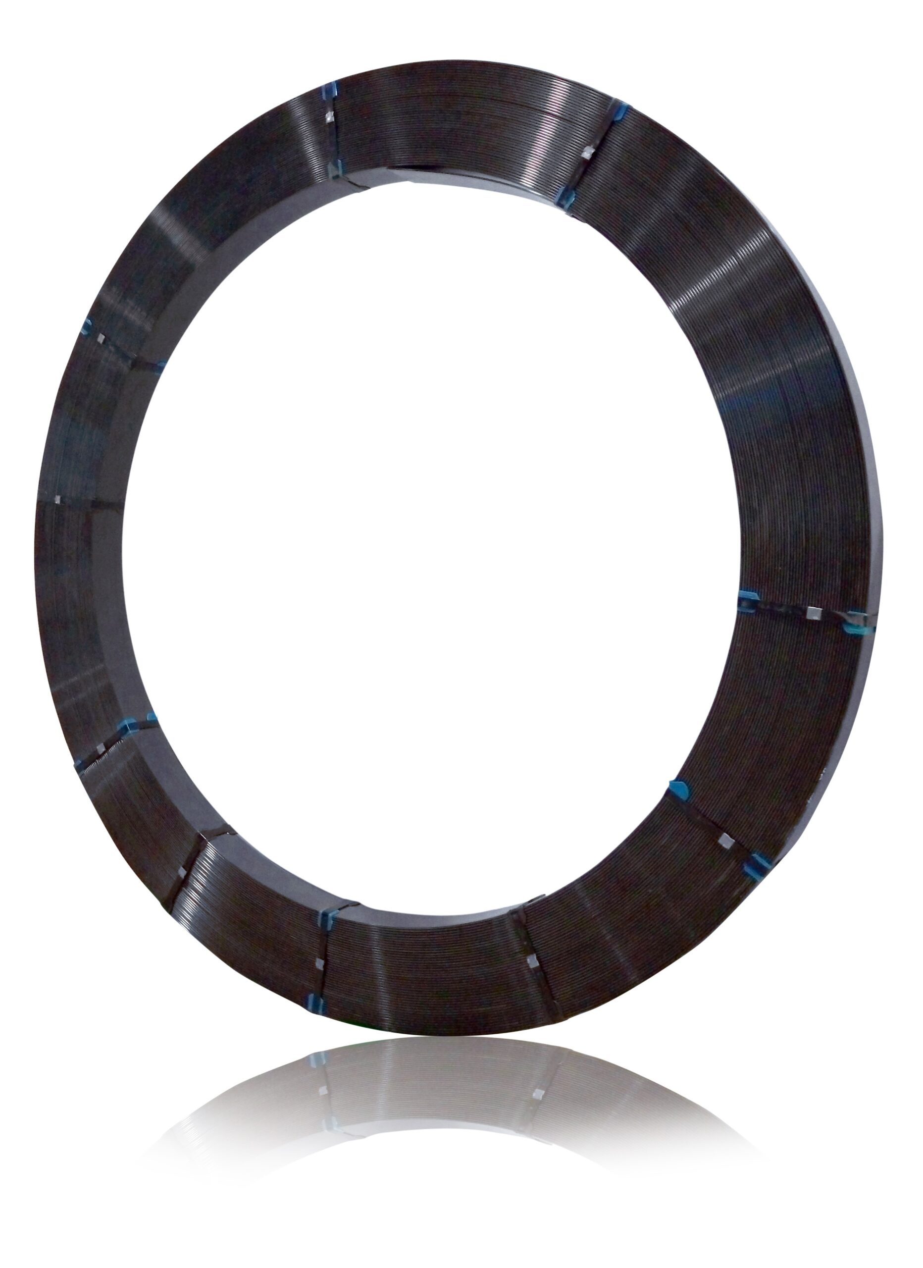
Let’s look closely at a niche but a critical topic for pultruded spar caps: Coiling.
Challenges of Coiling a Pultruded Carbon Fiber Spar Cap Profile
Coiling a pultruded carbon fiber spar cap is challenging due to the pultruded material’s inherent stiffness and rigidity. Unlike naturally flexible materials, pultruded carbon fiber composites are designed to maintain shape and resist bending. However, you need to coil them for transportation or other practical reasons. Here’s how the process generally works:
1. Understanding the Material Limits:
Flexibility: Determine the flexibility of the spar cap. The ability to coil without damaging the material depends on the spar cap’s thickness, width, and specific construction. Thinner or narrower spar caps might be more amenable to gentle coiling.
2. Stress Analysis: Conduct a stress analysis to understand the maximum strain the material can handle without causing micro-cracks or fiber breakage
3. Gradual Bending:
Slow Process: If the spar cap allows some bending, it should be done slowly and incrementally. Rapid or sharp bending can cause cracks or other damage.
Even Distribution: Apply force evenly along the length of the spar cap to avoid stress concentrations that can lead to damage.
Monitoring for Stress:
Observation: Continuously monitor the spar cap for signs of distress, such as whitening (in some resins), which indicates excessive stress.
Testing: After coiling, inspect the spar cap for any signs of damage. Non-destructive testing methods can be used to check for internal cracks or delamination.
4. Environmental Considerations:
Temperature: Perform the coiling at a suitable temperature. Some materials may become more flexible and less prone to cracking at higher temperatures.
Humidity: Control the environment to avoid any conditions affecting the material’s properties.
5. Transportation and Storage:
Secure: Once coiled, the spar cap should be securely fastened to prevent it from uncoiling unexpectedly.
Protected: Protect it from environmental factors that could cause damage over time.
6. Uncoiling:
Careful Release: When it’s time to uncoil the spar cap, do so carefully and slowly to prevent any sudden release of stress that could damage the material.
Coiling requires careful planning, appropriate equipment, and a deep understanding of the material’s properties and limitations.
To address the industry’s needs, BTU-TECH has developed an innovative pultrusion profile coiler that can operate as an uncoiler platform for managing all industry challenges.
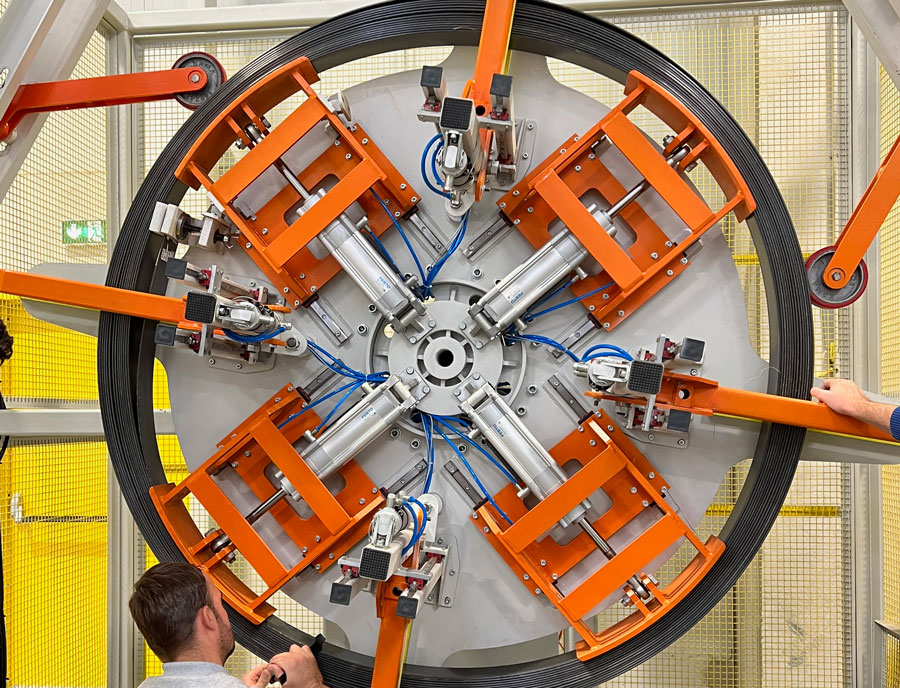
The Pultrusion Coiler’s inner diameter (ID) is electronically programmable. Four pneumatic support arms are equally spaced at 90 degrees to support the coil from the side at all times. The ID is electronically measured and displayed. In case of power or air loss, a mechanical brake holds the coil in place by fixing the ID such that the coil does not expand or contract. After the winding operation, the core shrinks to release the coil easily. The width of the pultruded profile is mechanically adjustable. Electronically programmable tensioner wheels ensure the coil does not expand during operation.
A metering wheel encoder calculates the total coil length and speed. With the touch of a button, the coiler becomes an uncoiler and can operate either in torque or speed mode.
A servo motor generates the necessary power for the coiler/uncoiler rotation operation. The motor torque or speed can be adjusted from the HMI touch panel. The HMI enables the operator to control the coiler remotely (wireless) from a tablet or smartphone. Both manual and full automatic operation is possible from the HMI.
Pay a visit to the “BTU-TECH Pultrusion Coiler” webpage for detailed product info and brochure.